|
Hi All
sorry for disturbing.
Maybe somebody in OK wants already know this. :) Please share this .file on relevant places, forums ...
Best regards, 9A4cw, Dejan
Member of 9A1CRS contest team.
This problem has been ongoing for years without a proper solution. Dozens of various "options" have been published, but none have fully resolved the issue—including factory recommendations to change the bias current on the driver stage transistors (pre-drivers) and replacing some resistors and diodes. By lowering the bias current according to these recommendations (on about 10 available radios), the pre-drivers (2SK2975) heated up slightly less, modulation on HF was good, on 50 MHz acceptable, but on 144 MHz completely unusable. The total output power was slightly lower depending on the band. The transistors simply overheat, causing desoldering (solder joints to fail) and lose contact. End of transmission (NO TX).
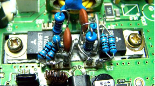
There are also some solutions using replacement transistors like the RD15HVF (which I have tested), which work well on HF but not at all on 144 MHz—the modulation is poor, boxy, dull, with no dynamics or high tones. I built this "ikebana" with classic components, with SMD parts, and with a custom board. The result was always partial. One unit worked well with this "solution"—but only one—making it more of an exception than a rule. The same advice applies here: don't buy transistors from unverified sellers on eBay and similar sites. You'll regret it immediately.
When one of the units came in for the third time with the same problem, I concluded there was no point in doing the same thing again—replacing or resoldering the transistors. I must note: this radio was not used with FT-8 mode, only had long CQ calls during contests. Also worth noting: on 8 out of 10 devices, the pre-drivers survived the overheating and worked fine after resoldering, as if they had just left the factory. Since the device proved excellent for contesting, I decided to solve the problem permanently—by any means. I even considered making a completely new PCB with a larger heatsink. Luckily, that turned out to be unnecessary.
|
| So what's the problem?
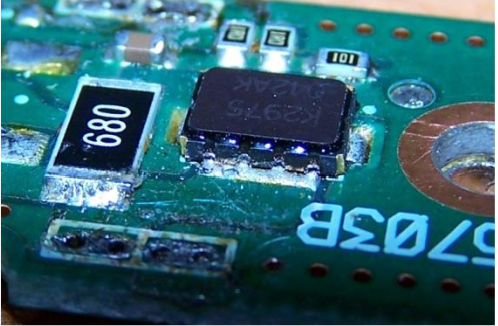
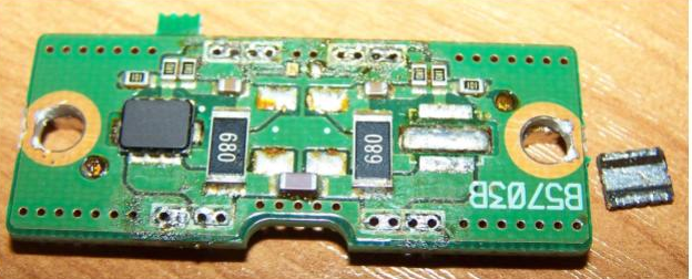
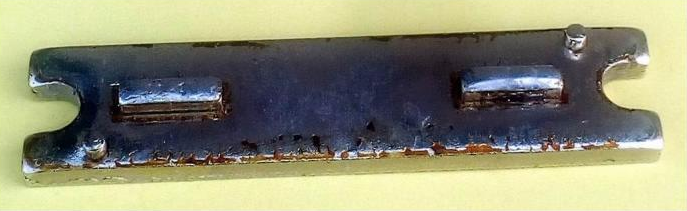
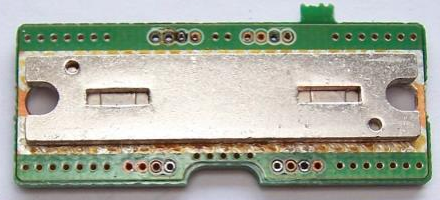
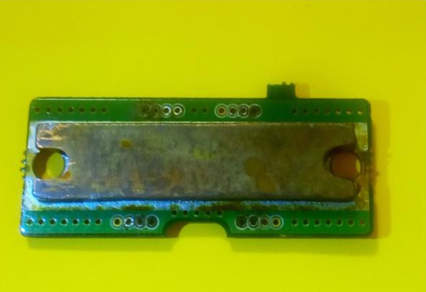
Careful observation of that small piece of metal to which the transistors are soldered—what the factory calls a "heatsink"—led me to conclude that an incredible mistake was made by the engineers. This mistake turned an otherwise excellent device into a "radio case" that was never resolved during its production lifespan. On that "heatsink," located under the pre-driver board, are two small metal bumps (blocks) where the source of the 2SK2975 transistors is soldered. Each is about the size of three match heads.
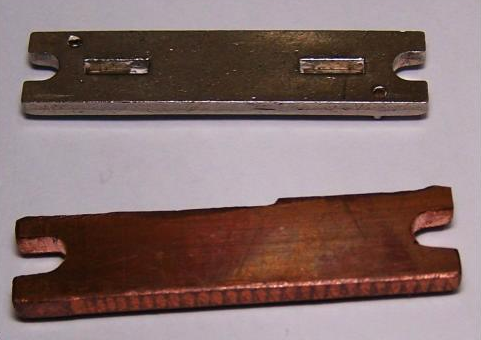
Those two tiny metal blocks are the only thing cooling the transistors How? Simple: if you look at the "heatsink" from below (Picture 6), you'll see it has two rectangular holes of the same width and height as the blocks on the top side. These blocks are punched out of the main heatsink body, and a thin metal sheet covers the holes left behind.
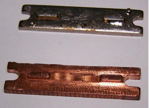
So what cools the transistors? The correct answer: nothing. The contact surface between the blocks and the heatsink body is less than 1mm. That negligible surface, along with the copper traces on the board, are the only things cooling those two "poor guys." This ends the myth that the 2SK2975 is a "problematic" and poor-quality transistor. Very few transistors would survive such torture without any real cooling. Unfortunately, this transistor is no longer manufactured, but it can be reliably replaced with the RD07MVS1. How to fix it? I made a new heatsink from copper using a milling process.
On this heatsink, the blocks are a single piece with the body of the heatsink and are fully flush with it—no gaps underneath—allowing full-surface heat transfer. With this heatsink, even after several minutes of full-power FM transmission, the transistor temperature did not exceed 75°C. With the original heatsink, it went over 180°C.
Total idle current must be 3.5–4.5 A—only then is the modulation good across all bands and the output power 100W. (Receive current draw is 1.5–1.6 A depending on frequency.)
Another, less ideal but still functional option is to fill the holes on the underside of the original heatsink using brazing (hard soldering). Of course, you'll need to remove the transistors first. Thermal paste under the heatsink is recommended.
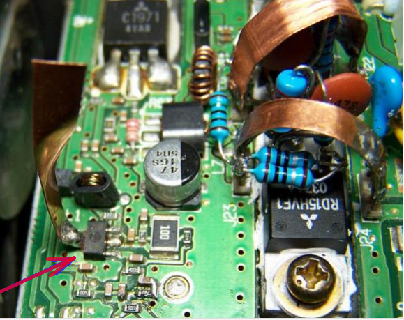
The 2SK2973 transistor also overheats significantly. This can be noticed during longer transmissions when modulation degrades.
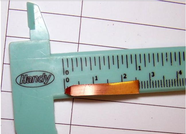
This can be easily solved by
soldering a copper strip (4–5mm wide, 2–3cm long) to the source of the
transistor. The "little guy" can breathe more easily now. This transistor also, in the original configuration, has no cooling.
Conclusion: Do not change anything in the device except the heatsink. Do not touch the bias current settings or anything else. Simply replace the heatsink physically, and everything will be fine.
Good luck, 9A4CW, Dejan
|
 pic
1.
pic
1. pic2.
pic2.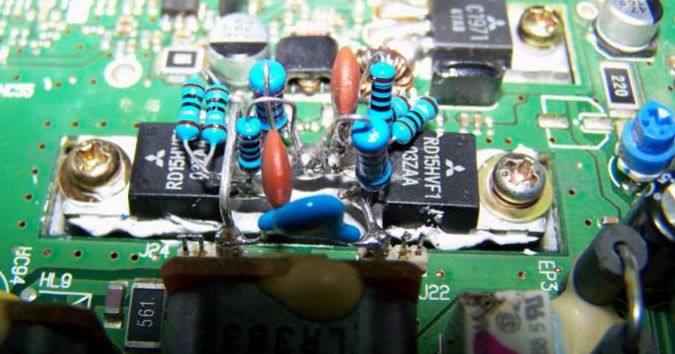 pic
3.
pic
3. pic
4.
pic
4. pic
5..
pic
5.. pic
6.
pic
6. pic
7.
pic
7. pic
8.
pic
8. pic
9.
pic
9. pic
10.
pic
10. pic 11.