|
Although I don't think, that such arrangement is the best way for VHF Contesting, my design of 3 antennas switch for 2m was quite popular article at OK2KKW web. However, who want to use more directions and even for higher bands, the original design is not enough to cover such needs. Due to that I have prepared new PCB, suitable for control of GHz relay 1/6 with SMA connectors, produced by more companies, which is possible to buy either on E-bay, or on different e-shops with used microwave HW.
By purchase of such relay was fixed first part of the task. The second - control part of the antenna switch has designed as simple (one sided) PCB of 50x60mm size, which is placed in screened box beside antenna relay somewhere below operator table. However - because the control unit should be as flexible as possible - it should control as well as two as even 6 receiving antennas, the control unit is designed to have a possibility place into an antenna box manual switch, which can preset length of the cycle - from 2 to 6 aerials. Then you can select step by step all used antennas by simple click on one control button, placed in the small control box beside transceiver. Possible questions to functionality of such IC are described in original article from 2008 year. Picture of operator table with control box of the antenna switch is for example here:
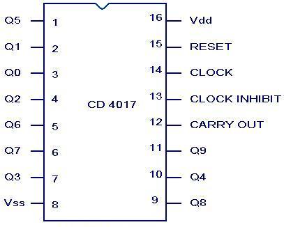
Controller circuit is as simple as possible. It use CMOS IC CD4017, which by BS170 FET switches activates step by step appropriate coils of the antenna relay and activates monitoring LEDs. When are used less, than 6 antennas, you can simply limit nr of cycle steps by interconnection of next higher output of the IC with the reset PIN (15). On the picture is as the sample, control unit adjusted for 4 antennas, where is on the PCB by wire jumper interconnected the reset input (PIN15) with fifth output (PIN10). Note: output 1 is assigned as Q0, output 2 as Q1 etc.. In such case you can on the PCB use wire interconnection (red on the schema). Everything is well visible on the photo of real construction. Output for control box (consist of switch button and LEDs) is connected by more wires cable. In case, that some of LED (white or blue) will be too shiny, simply connect additional suitable resistor in the series.
Supplying of control board is 24 to 27V DC, the same as what is requested for relay. Do not remove designed stabilizer 78L12.
Next pics shows PCB and real construction of switch adjusted for 4 antennas - btw: for fun - you may try to discover my failure during soldering - yes, the outputs for LED1 and LED2 have short interconnection by tin, hi.
Cu soon on VHF! OK1VPZ |


